I've been hunting for a useful project to do with my Raspberry Pi, and found out that there were two major projects centered around getting something similar setup.
Ambi-TV: https://github.com/gkaindl/ambi-tv
Hyperion: https://github.com/tvdzwan/hyperion/wiki
With both software projects, you take an HDMI signal, convert it to analog and then capture the analog signal to analyze. Once the signal is analyzed a string of addressable LED's is programmed to match what the borders are colored.
I did my initial setup using both software packages but in the end preferred using Hyperion for it's easy of use of configuration and results.
Necessary Hardware
I purchased the following (links point to where I purchased):- 3 meters of addressable LPD8806 LED lighting strips
- 5V 10A power supply
- Power adapter plug
- 4-pin JST SM plug
- Cheap DC60 USB analog video grabber
- HDMI splitter
- HDMI to Composite adapter
Other stuff I already had on hand that was needed:
- Soldering tools
- Spare prototyping board
- Raspberry pi w/ case
- Extra HDMI cables
- Analog Composite cable
- Spare wires
Electronics Setup
Once everything arrived, I soldered a handful of wires to a prototyping board so that I could house more of the pieces in the raspberry pi case. I used a cut up micro USB cord to provide power from the 5V rail and ground to the pi itself and then also to one end of the 4 pin JST adapter.
 |
| Prototyping board, probably this size is overkill, but I have flexibility for future projects to add on now. |
GPIO connectors
The clock and data lines on the LPD8806 strip (DI/CI) matched up to these pins on the raspberry pi:Pin 19 (MOSI) LPD8806 DAT pin
Pin 23 (SCLK) LPD8806 CLK pinCase
Once I got everything put into the pi properly, I double checked all the connections and closed up the case. |
| My pi case with the top removed and an inset put in for holding the proto board |
 |
| Whole thing assembled |
TV mounted LEDs
I proceeded to do the TV. I have a 46" set, which works out to 18 LEDs on either side and 30 LEDs on the top and bottom. I cut up the LED strips and used double sided tape to affix to the TV. Once the LED strips are cut up you have to solder 4 pins from the out end of one strip to the in end of another strip. I'd recommend looking for some of the prebuilt L corner strips if you do this. I didn't use them and it was a pain to strip and hold such small wires in place to solder in the small corners. All of the pins that are marked "out" on one end of the LED strip get connected to the "in" end on the next strip. |
| Back of TV w/ LEDs attached |
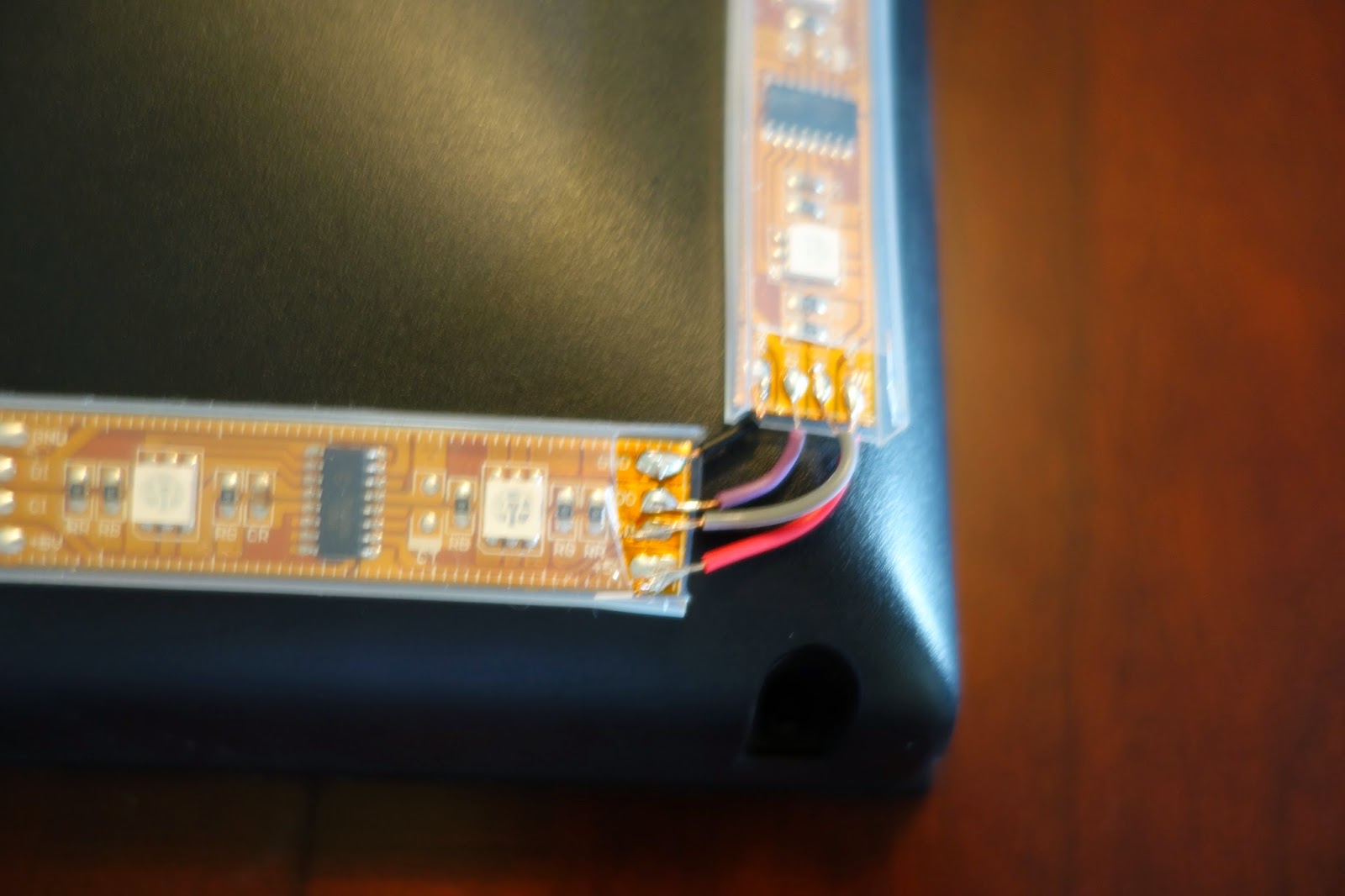 |
| Corner with wires soldered on from out to in |
External hardware Setup
From the output of my receiver that would be going to my TV, I connect it to the input of the HDMI splitter.The HDMI splitter's primary output goes to the TV.
The secondary output goes to the HDMI2AV adapter.
The HDMI2AV adapter's composite video output gets connected to the video input of the USB grabber.
The USB grabber is plugged directly into the raspberry pi.

Software Setup
Once all the HW was together I proceeded to get the software set up. I originally had an up to date version of raspbian wheezy installed. It included an updated kernel (version 3.10). I managed to set everything up using it except the grabber, but then discovered that there were problems with the USB grabber I purchased.
Plugging it in causes the box to kernel panic. The driver for the USB grabber has made it upstream in kernel version 3.11, so I expected it should be usable in 3.10 with some simple backporting tweaks, but didn't narrow it down entirely.
Plugging it in causes the box to kernel panic. The driver for the USB grabber has made it upstream in kernel version 3.11, so I expected it should be usable in 3.10 with some simple backporting tweaks, but didn't narrow it down entirely.
I did find out that kernel 3.6.11 did work with an earlier version of the driver however, so I re-did my install using an older snapshot of raspbian. I managed to get things working there, but would like to iron out the problems causing a kernel panic at some point.
USB Grabber instructions
The USB grabber I got is dirt cheap but not based off the really common chipsets already supported in the kernel with the versions in raspbian, so it requires some extra work.
- Install Raspbian snapshot from 2013-07-26. Configure as desired.
- git clone https://github.com/gkaindl/ambi-tv.git ambi-tv
- cd ambi-tv/misc && sudo sh ./get-kernel-source.sh
- cd usbtv-driver && make
- sudo mkdir /lib/modules/3.6.11+/extra
- sudo cp usbtv.ko /lib/modules/3.6.11+/extra/
- sudo depmod -a
Hyperiond Instructions
After getting the grabber working, installing hyperion is a piece of cake. This will set up hyperiond to start on boot.
- wget -N https://raw.github.com/tvdzwan/hyperion/master/bin/install_hyperion.sh
- sudo sh ./install_hyperion.sh
- Edit /etc/modprobe.d/raspi-blacklist.conf using nano. Comment out the line with blacklist spi-bcm2708
- sudo reboot
Hyperion configuration file
From another PC that has java (OpenJDK 7 works on Ubuntu 14.04)
- Visit https://github.com/tvdzwan/hyperion/wiki/configuration and fetch the jar file.
- Run it to configure your LEDs.
- From the defaults, I particularly had to change the LED type and the number of LEDs around the TV.
- My LEDs were originally listed at RGB but I later discovered that they are GRB. If you encounter problems later with the wrong colors showing up, you can change them here too.
- Save the conf file and scp it into the /etc directory on your pi
- sudo /etc/init.d/hyperiond restart
Test the LED's
- Plug in the LEDs and install the test application at https://github.com/tvdzwan/hyperion/wiki/android-remote
- Try out some of the patterns and color wheel to make sure that everything is working properly. It will save you problems later diagnosing grabber problems if you know things are sound here (this is where I found my RGB/GRB problem).
 |
| Test pattern |
Set up things for Hyperion-V4L2
I created a script in ~ called toggle_backlight.sh. It runs the V4L2 capture application (hyperion-v4l2) and sets the LEDs accordingly. I can invoke it again to turn off the LEDs. As a future modification I intend to control this with my harmony remote or some other method. If someone comes up with something cool, please share.
#!/bin/sh
ARG=toggle
if [ -n "$1" ]; then
ARG=$1
fi
RUNNING=$(pgrep hyperion-v4l2)
if [ -n "$RUNNING" ]; then
if [ "$ARG" = "on" ]; then
exit 0
fi
pkill hyperion-v4l2
exit 0
fi
hyperion-v4l2 --crop-height 30 --crop-width 10 --size-decimator 8 --frame-decimator 2 --skip-reply --signal-threshold 0.08&
That's the exact script I use to run things. I had to modify the crop height from the defaults that were on the directions elsewhere to avoid flicker on the top. To diganose problems here, I'd recommend using the --screenshot argument of hyperion-v4l2 and examining output.
Once you've got it good, add it to /etc/rc.local to start up on boot:
su pi -c /home/pi/toggle_backlight.sh
Test It all together
Everything should now be working.
Here's my working setup:
Cool project, could we get a list of materials and suppliers?
ReplyDeleteThanks Wayne! I've updated the post to call out all the HW I used more clearly, including stuff I had on hand. The links call out to adafruit and amazon to the exact items i've purchased now too.
ReplyDelete